Arduino IDEを使用して、4つのボタンがあり、各ボタンを押すと指定のテキストやキーが表示されるスケッチを作成します。
4個のボタンを「単一文字」「複数文字」「コンビネーションキー」に割り当ててみます。
ここまで出来るようになると、一般に販売されているマクロキーボードなどにかなり近くなりますのでぜひ頑張って試してみてください!
必要なもの
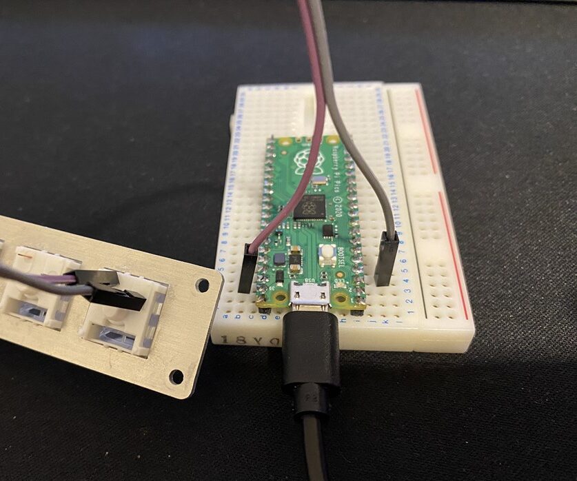
- Arduino Pro Micro・Raspberry Pi PiconなどArduinoIDEに対応しておりHID準拠の物
- ブレッドボード(あると便利です)
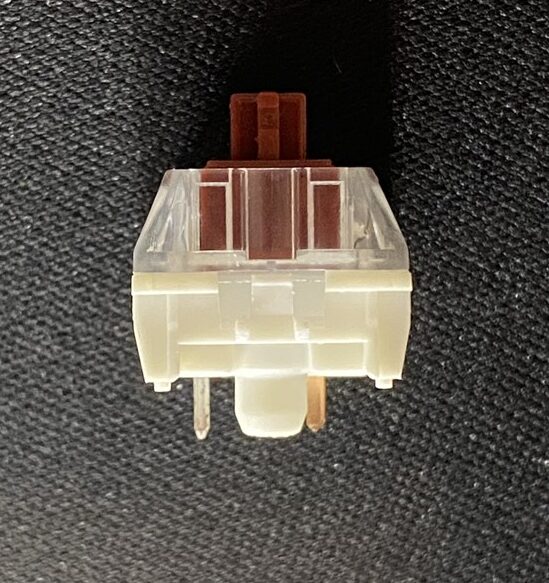
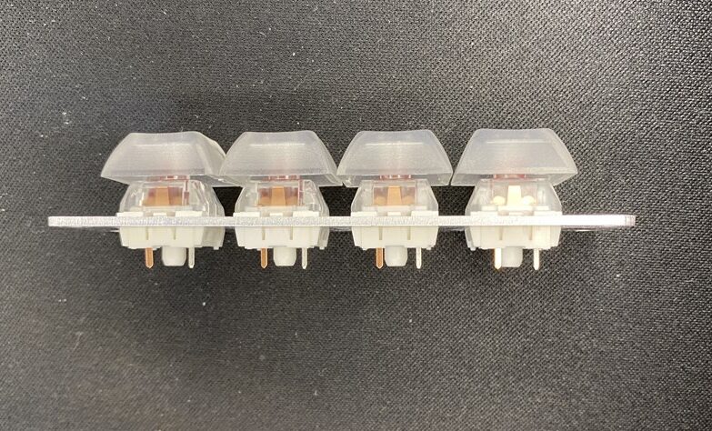
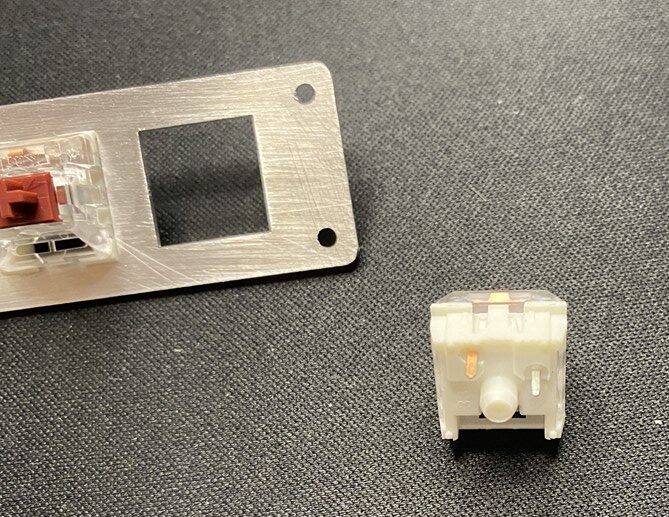
- 4つのボタン(スイッチ)・CherryMX互換のメカニカルキースイッチなど
- 接続用のジャンパーワイヤ
リンク
リンク
配線図
- ボタン1: デジタルピン 2
- ボタン2: デジタルピン 3
- ボタン3: デジタルピン 4
- ボタン4: デジタルピン 5
- 各ボタンの片方の端子はGNDに接続し、もう片方の端子は対応するデジタルピンに接続します。
スケッチ
以下のスケッチをArduino IDEにコピーして、Pro MicroやRaspberry Pi Picoなどにアップロードしてください。
#include <Keyboard.h>

// ボタンのピン番号
const int button1Pin = 2;
const int button2Pin = 3;
const int button3Pin = 4;
const int button4Pin = 5;

// ボタンの状態
int button1State = 0;
int button2State = 0;
int button3State = 0;
int button4State = 0;

void setup() {
  // ボタンピンを入力に設定
  pinMode(button1Pin, INPUT_PULLUP);
  pinMode(button2Pin, INPUT_PULLUP);
  pinMode(button3Pin, INPUT_PULLUP);
  pinMode(button4Pin, INPUT_PULLUP);

  // キーボードの初期化
  Keyboard.begin();
}

void loop() {
  // ボタンの状態を読み取る
  button1State = digitalRead(button1Pin);
  button2State = digitalRead(button2Pin);
  button3State = digitalRead(button3Pin);
  button4State = digitalRead(button4Pin);

  // ボタン1が押されたら "Hello Arduino" を表示
  if (button1State == LOW) {
    Keyboard.print("Hello Arduino");
    delay(500); // デバウンス対策
  }

  // ボタン2が押されたら 'A' を表示
  if (button2State == LOW) {
    Keyboard.write('A');
    delay(500); // デバウンス対策
  }

  // ボタン3が押されたら Ctrl+C を送信
  if (button3State == LOW) {
    Keyboard.press(KEY_LEFT_CTRL);
    Keyboard.press('c');
    delay(100);
    Keyboard.releaseAll();
    delay(500); // デバウンス対策
  }

  // ボタン4が押されたら "See you" を表示
  if (button4State == LOW) {
    Keyboard.print("See you");
    delay(500); // デバウンス対策
  }
}
スケッチの行ごとの説明
- ヘッダファイルのインクルード
#include <Keyboard.h>
- Keyboard.hライブラリをインクルードして、キーボードのエミュレーション機能を使用します。
- ボタンのピン番号の定義
   const int button1Pin = 2;
   const int button2Pin = 3;
   const int button3Pin = 4;
   const int button4Pin = 5;
- 各ボタンに対応するデジタルピン番号を定義します。
- ボタンの状態を保存する変数の定義
   int button1State = 0;
   int button2State = 0;
   int button3State = 0;
   int button4State = 0;
- 各ボタンの状態を保存するための変数を定義します。
- ボタン数を変更している場合は、追加削除してください。
- setup関数
   void setup() {
     pinMode(button1Pin, INPUT_PULLUP);
     pinMode(button2Pin, INPUT_PULLUP);
     pinMode(button3Pin, INPUT_PULLUP);
     pinMode(button4Pin, INPUT_PULLUP);
     Keyboard.begin();
   }
- 各ボタンのピンを入力モード(内部プルアップ抵抗)に設定し、Keyboardライブラリを初期化します。
- ボタン数を変更している場合は、追加削除してください。
- loop関数
   void loop() {
     button1State = digitalRead(button1Pin);
     button2State = digitalRead(button2Pin);
     button3State = digitalRead(button3Pin);
     button4State = digitalRead(button4Pin);
- 各ボタンの状態を読み取ります。
- ボタン数を変更している場合は、追加削除してください。
- ボタン1の処理
   if (button1State == LOW) {
     Keyboard.print("Hello Arduino");
     delay(500);
   }
- ボタン1が押されたら(LOW)、”Hello Arduino” を送信し、500ms待機してデバウンス対策をします。
- ボタン2の処理
   if (button2State == LOW) {
     Keyboard.write('A');
     delay(500);
   }
- ボタン2が押されたら(LOW)、’A’ を送信し、500ms待機してデバウンス対策をします。
- ボタン3の処理
   if (button3State == LOW) {
     Keyboard.press(KEY_LEFT_CTRL);
     Keyboard.press('c');
     delay(100);
     Keyboard.releaseAll();
     delay(500);
   }
- ボタン3が押されたら(LOW)、Ctrl+Cを送信し、500ms待機してデバウンス対策をします。
- ボタン4の処理
   if (button4State == LOW) {
     Keyboard.print("See you");
     delay(500);
   }
- ボタン4が押されたら(LOW)、”See you” を送信し、500ms待機してデバウンス対策をします。
このスケッチを使うことで、各ボタンを押すと指定のテキストやキーを送信するマクロキーボードが作成できます。
リンク
まとめ
今回の複数キーにアクションを振り分けることが出来た時点で、一般的なマクロキーボードとほぼ同様の操作が可能になります。
また、前回の1キーでキーカウントによる動作制御も各キーに取り入れることも可能です。
各ボタンの処理の中身を書き変えればOKです。
例:1つ目のボタンであれば
if (button1State == LOW) {
以降に前回のキーの操作部分のソースを張り付ければOKです。
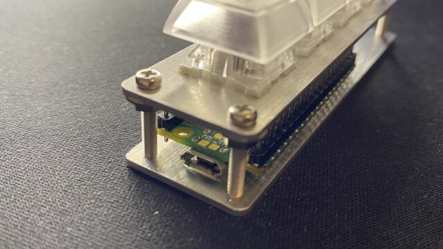
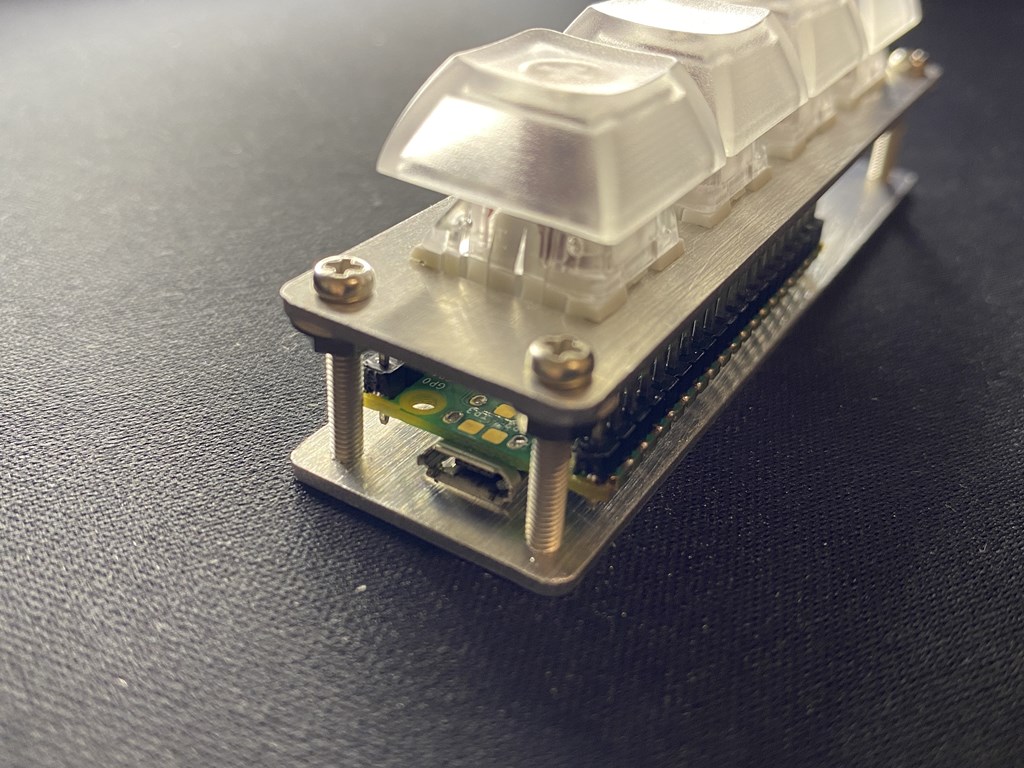
ちなみに、今回アップした写真のキーはKailhのCopper軸です。CherryMX互換で軸の種類もかなり豊富でCherryMXより価格も安く、最近のNISSYのお気に入りのキーです。
※今回の物には付けていませんがLEDも追加できるようになっています。






コメント